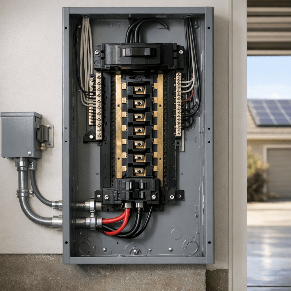
The NEC 120% rule is a safety limit that governs how much backfed solar current you can add to a panelboard without overheating the busbar. If you design or sell PV, understanding this rule is essential to pass plan review, avoid field change orders, and ensure long-term reliability. Below you will find the plain-English calculation, how it relates to the 125% continuous-load rule, where breaker position matters, and practical ways to stay compliant.
Why the 120% rule exists and what it prevents
In a traditional service panel, current flows from the utility through the main breaker into the busbar and out to branch circuits. When you add a PV breaker on the load side, the inverter can also backfeed the busbar. In rare but credible scenarios, utility current and inverter current can combine to stress sections of the bus beyond its rating.
The 120% rule limits the sum of overcurrent devices that can feed the busbar. By capping the total rating that can supply the bus, the code reduces the risk of overheating, insulation damage, and arc faults at the bus stabs. This keeps equipment within tested thermal limits and gives inspectors a straightforward pass-fail check without requiring complex load modeling for every installation.
Practically, this affects how large a PV breaker you can install in common 100 A to 200 A residential panels and how you place that breaker on the bus so heat is not concentrated near the main.
Where the 120% rule lives in the NEC and what changed since 2017
The 120% rule applies to load-side interconnections covered in NEC 705.12. The language and numbering shifted over editions, so you may see references like 705.12(D) in older materials. The principle stayed the same: if you connect PV on the load side, the busbar may be used up to 120% of its rating when certain conditions are met.
Many authorities having jurisdiction adopted the 2017 NEC, so you might still hear installers say 120 rule NEC 2017. Later editions, including 2020, reorganized Article 705 and clarified options for breaker location and supply-side connections. Local adoption varies, so the exact subsection numbering and any local amendments can differ.
Key takeaway: for a typical residential load-side interconnection, you must ensure the busbar rating, main breaker, and the PV backfeed breaker satisfy the 120% limit, and you must follow any placement requirements your AHJ enforces. For local enforcement details, check your AHJ’s requirements for solar site inspections.
How the 120% rule works – the core calculation
The load-side 120% test is straightforward once you know the numbers on the panel label. You can capture these nameplate ratings during a solar site assessment.
- Step 1 – Find the panelboard bus rating in amperes.
- Step 2 – Multiply that bus rating by 1.2.
- Step 3 – Subtract the main breaker rating.
- Step 4 – The result is the maximum allowed PV backfeed breaker size for that panel, assuming permitted placement and no other sources.
Example with a 200 A bus and a 200 A main:
200 A x 1.2 = 240 A. 240 A – 200 A = 40 A. You can install up to a 40 A PV breaker under the 120% rule in this configuration.
| Busbar rating (A) | Main breaker (A) | Max PV breaker under 120% (A) |
|---|---|---|
| 100 | 100 | 20 |
| 125 | 125 | 25 |
| 150 | 150 | 30 |
| 200 | 200 | 40 |
This table assumes a single PV source, PV breaker installed at the opposite end of the bus from the main when required, and no other generation sources. Always verify panel labeling, any feed-throughs, and local amendments before finalizing your design.
Breaker placement and why it matters
The 120% rule is about equipment ratings, not simple arithmetic of real-time currents. Still, where you place the PV breaker can affect heat distribution on the busbar. Many jurisdictions require or strongly prefer the PV backfeed breaker at the opposite end of the bus from the main breaker to reduce the chance of concentrating thermal stress in one area.
Some panels allow a “center-fed” layout or have busbar restrictions called out on the labeling. Follow the panel’s instructions regarding which slots are acceptable for backfeed, and install any required hold-down kits. If your AHJ mandates opposite-end placement, plan your layout accordingly before submitting drawings. For a field-ready checklist of what inspectors look for around busbars and backfeed breakers, see solar site inspections.
The 125% rule and how it fits with the 120% rule
Do not confuse the NEC 120% rule with the NEC 690 125% rule. The 125% rule applies to continuous current when sizing conductors and overcurrent protection for inverters and PV circuits. In practice, you size the inverter output circuit at 125% of its continuous rated current, then you check that breaker size against the 120% limit of the panelboard.
Example: If your inverter outputs 32 A continuous, 32 A x 125% = 40 A. You would select a 40 A OCPD and conductors sized for that current. Next, verify that your panel can accept a 40 A PV breaker under the 120% busbar limit. If it cannot, pursue one of the options below.
What to do when you exceed the 120% limit
If the calculation says your PV breaker is too large for the existing panel, you have several code-compliant paths. Your AHJ and utility will influence which one is best.
- Reduce the main breaker rating – If a load calculation under NEC 220 shows it is permitted, downsizing the main (for example from 200 A to 175 A) creates PV headroom without changing the bus.
- Upgrade the panelboard or service equipment – A panel with a higher busbar rating allows a larger PV breaker and may provide more slots and thermal margin.
- Use a supply-side connection – A line-side tap connects on the service conductors ahead of the main. This bypasses the load-side 120% limit, but has its own rules and utility coordination requirements.
- Add a dedicated generation panel or subpanel – Reconfigure so the PV ties into equipment designed for higher backfeed current or so loads are redistributed to respect the 120% limit.
- Leverage power control systems where permitted – In some jurisdictions and code editions, listed control systems can limit export current. Only use this if your AHJ recognizes the method and you follow the exact listing and settings.
Whichever path you choose, document the method in your plans and include manufacturer instructions for any special kits, taps, or hold-downs the inspector will look for. To reflect these outcomes in pricing and scope, see how to write a solar sales proposal.
Load-side vs supply-side interconnections
A load-side interconnection lands the PV breaker on the customer’s distribution, inside a panelboard or subpanel. This is where the NEC 120% rule applies most often for residential work. It is generally straightforward and fast to permit when the bus rating and breaker placement check out.
A supply-side interconnection, sometimes called a line-side tap, connects the PV to the service conductors ahead of the main breaker. This avoids the 120% busbar constraint, but introduces other code requirements for tap length, conductor protection, and enclosures. Utilities also have specific metering and disconnect rules for supply-side connections. Choose this route when the panel is too small and a service upgrade is impractical.
Pre-permit checklist
When scoping with homeowners, use these questions to ask during a solar consultation to capture main breaker size, busbar rating, and available spaces early.
- Confirm the panel’s busbar rating and main breaker size from the labeling.
- Run the 120% calculation and verify PV breaker placement rules for your AHJ.
- Apply the 125% rule to inverter output to size conductors and OCPD.
- Check space for hold-down kits and any restricted slots noted by the manufacturer.
- If over limit, pick a strategy: smaller main, panel upgrade, supply-side, or reconfiguration.
- Attach manufacturer instructions and one-line diagrams that show the chosen method.
FAQ
What is the NEC 120% rule?
The NEC 120% rule limits how much generation you can backfeed into a panelboard on the load side. The combined ratings of overcurrent devices that can supply the busbar are capped at 120% of the busbar’s ampere rating. This prevents overheating and maintains equipment within tested limits during abnormal but possible current flows.
How does the 120% rule work in practice?
Multiply the panel’s bus rating by 1.2 and subtract the main breaker rating. The remainder is the maximum PV backfeed breaker allowed, assuming code-compliant placement and no other sources. Example: 200 A bus with 200 A main gives 40 A of PV backfeed allowance. Always check local requirements for PV breaker location on the bus.
What is the 125% rule for circuit breakers?
The 125% rule applies to continuous loads like inverter output. You size conductors and the overcurrent protective device at 125% of the inverter’s continuous current. After sizing the PV breaker with the 125% rule, verify it still fits within the panel’s 120% busbar allowance. The two rules work together, they do not replace each other.
How do you calculate the 120 rule?
Use this sequence: find the busbar rating, multiply by 1.2, subtract the main breaker rating, and round to a standard breaker size not exceeding the result. If that size is not available or is too large for placement rules, choose a smaller breaker or change your interconnection method.
Does breaker position matter for the 120% rule?
Yes, many AHJs require the PV backfeed breaker at the opposite end of the bus from the main to spread heat. Some panels have restricted slots or labeling that dictates where backfeed is allowed. Incorrect placement can cause inspection failure even if your arithmetic passes the 120% test.
What changed between the 120 rule NEC 2017 and later editions?
The core concept stayed the same, but Article 705 was reorganized and clarified in later editions like 2020. Numbering and some options for interconnection methods moved. Always check which NEC edition your jurisdiction enforces and follow any local amendments or utility service rules.
Plan faster with digital design
You can surface 120% constraints early by capturing panel label data during remote site analysis and reflecting it in your single-line design. Interactive 3D simulations and accurate takeoffs help you align inverter selection, PV breaker size, and interconnection method before permit submittal. That reduces redesign risk and speeds up approvals without committing to a service upgrade too soon. If you’re deciding what to capture during a quick site survey versus a full assessment, read site survey vs. site assessment.